Quick User Guide
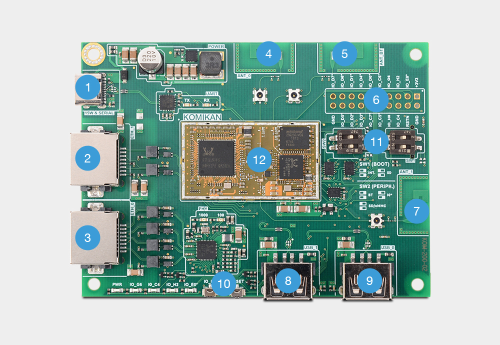
1 - USB – C (Power supply, UART console)
2 - Ethernet port 100/10 Mbps
3 - Ethernet port 1000/100/10 Mbps
4 - WiFi antenna (2.4/5G)
5 - Bluetooth antenna
6 - GPIO header
7 - WiFi antenna (2.4/5G)
8 - USB type A (2.0)
9 - USB type A (2.0)
10 - Buttons (Reset, GPIO)
11 - Dip switches (bootstrap and peripheral selection)
12 - Komikan module
Switches
There are SW1(BOOT) and SW2(PERIPH.) switches. Here is explanation.
Boot
- Boot from internal flash - SW1 both switches off.
- Boot from SD card - SW1 both switches on.
Periphery
- Turn on Bluetooth - SW2 both switches off.
- Turn on SD/eMMC - SW2 both switches on.
- Turn on GPIO - SW2 1st switch off, 2nd switch on.
Power on
Only convenient way to power up your Komikan is by connecting it to a USB power source (e.g. your computer) by using a USB to USB-C cable. A single LED (named PWR on our development kit) should light up upon powering. Give it at least 30 seconds to boot.
Link up
Now that we powered Komikan on, let’s connect it via lan port. Configure your computer's network interface with 192.168.1.254 IP address and 255.255.255.0 netmask. Make sure that other devices on your network are not using this subnet! If everything is done correctly you should be able to reach Komikan via the default IP address of 192.168.1.1
Log in
Komikan is now reachable, so let’s login via ssh:
ssh root@192.168.1.1
Or via telnet:
telnet 192.168.1.1
Or via your internet browser with the following URL:
http://192.168.1.1
By default Komikan does not have password set so when logging in only enter username “root” and leave password field empty.